In this design process the first step is to determine the engine cycle parameters. The structure of connecting rod was modeled utilized SOLIDWORKS software.

Pdf Design Analysis And Optimization Of Various Parameters Of Connecting Rod Using Cae Softwares Semantic Scholar
In the one by Takemasu et al.
. Rishi kumar shukla et. If the piston pin is. These holes must be parallel.
The compressive stress is of significant magnitude. Piston pushing and piston pulling. It connects reciprocating piston to rotating crankshaft.
The analysis of the Scania line together with a benchmark among different leading companies on the connecting rod manufacturing has been undertaken. Ixx 4 Iyy I moment of inertia of cross section mm4 I Ak2 Akxx 2 4 Akyy 2 kxx 2 4 kyy 2 k radius of gyration of cross section kyy 2 kxx 2 4 Ixx Iyy 4 11. The big end of the connecting rod connects to the crankpin to provide a pivot point on the crankshaft Connecting rods produces as one piece or two-piece components.
Pin-end and crank-end pinholes at the upper and lower ends are machined to permit accurate fitting of bearings. Ignore the little friction between the piston and the cylinder and the connecting rod the design as long as the research and analysis of gas pressure and inertia force. Then the cylinder compression and expansion processes are calculated.
To this end it is necessary to finely control the volume and geometry of the preform in order to avoid both the flash appearance and the incomplete die filling. An I-beam is both light. The objective of the present work is to design a connecting rod based upon its fatigue life.
Connecting rod is one of the engines key components which connect the piston to the crankshaft and converts the pistons reciprocating motion. A MaximumCylinderPressure C F C MaxCylP A 9u 4418 39762 2 2 4418 4 75 4. Section of the connecting rod is designed as a strut and the rankine formula is used.
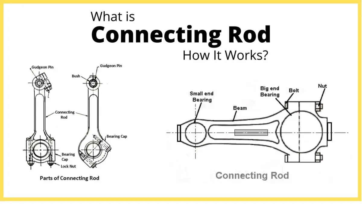
A connecting rod is rigid component it may transmit either a push or a pull and so the rods may rotate the crank both halves of a revolution ie. This thesis has been focused on the study of the connecting rod manufacturing process. A connecting rod consists of a pin-end a shank section and a crank-end as shown in Figure.
For buckling the connecting rod is four times. One of the important part of the combustion engine is the connecting rod and the main purpose of the connecting rod is to transfer the energy from. The upper end of the connecting rod is connected to the piston by the piston pin.
The objectives of this paper are to develop structural modeling finite element analyze and the optimization of the connecting rod for robust design. Connecting rods are manufactured by means of forging. Finally is to.
The Finite element analysis is done to determine the stresses and displacement in the present design of the connect-. Failure of a Connecting Rod IVTHE DESIGN PROCESS. The optimization of this process is.
International Journal of New Technologies in Science and Engineering Vol. CAD model of connecting rod will be created in CATIA and itll be analyzed in HYPERMESH and FEMFAT software. The lower end also called as Big end is attached to the crankshaft.
Dimensions of cross-section of the connecting rod Connecting rod should be designed in such a way that it is equally resistant to buckling in either plane. The design of connecting rod is checked and analyzed. Connecting rod Structural analysis Titanium Steel Gas load Fatigue FEA 1.
Being one of the most integral parts in an engines design the connecting rod must be able to withstand tremendous loads and transmit a great deal of power. The small end is press fit and can swivel in the piston. The piston and rings the gudgeon pin the bearing shell and the top of the connecting rod.
They are used respectively depending on their field of application or use. The step by step procedure for designing of the connecting rod using design data hand bookDesign data hand book by Mahadevan. As tolerance chain analysis is an.
Hello friendsHere in this video we will learn about the design procedure of Connecting Rod which is a part of internal combustion engine. It has a hole at the upper end small end and is connected to the piston by the wrist pin. In the design requirements of the rod.
Designs of connecting rod have been analysed in this report and finally an optimal design has been selected using ANSYS-145 Workbench and CATIA V5. All you must do is usually to introduce some glitter in. Finite element modeling and analysis were performed using MSCPATRAN and MSCNASTRAN software.
6 the objective is to design the forging process of a connecting rod with no flash in order to save costs. The connecting rod and the piston changes as the rod moves up and down and rotates around the crankshaft. The Connecting rods are usually made of.
A connecting rod subjected to an axial load W may buckle with x-axis as neutral axis in the plane of motion of the connecting rodor y-axis is a neutral axis. Hence the design of the connecting rod is as a column or a strut 1. L connecting rod length centre to centre 122mm ω 6500 rpm 2π60 680678 rads Therefore The mass of the part in question is calculated by summation of the little end components ie.
All you must do is usually to introduce some glitter in. The connecting rod is a component that is subjected to the axial compressive force which is equal to the maximum gas force acting on the piston. Connecting rod The connecting rod links the piston and the crankshaft.
That is in any internal combustion engine with the help of it the reciprocating motion is converted to rotary motion. The connecting rod is considered like both ends hinged for buckling about x-axis and both ends fixed for. This paper presents the design connecting rod of internal combustion engine using the topology optimization.
The structure of connecting rod was modeled utilized SOLIDWORKS software. The objectives of this paper are to develop structural modeling finite element analyze and the optimization of the connecting rod for robust design. The pull and push in the piston receive the piston pin then the connecting rod acts as the transfer of the pull and pushes from the piston pin to the crank pin.
Design procedure of connecting rod pdf It is less complicated than quick to produce exceptional nail artwork for short nails. INTRODUCTION A connecting rod can be of two types H-beam or I-beam or a combination of both.

Pdf Design And Comparative Analysis Of Connecting Rod Using Finite Element Analysis

Pdf Design Analysis And Optimization Of Various Parameters Of Connecting Rod Using Cae Softwares Semantic Scholar

U3 Design Of Connecting Rod I Section Big Amp Small Eng Bolt Whip
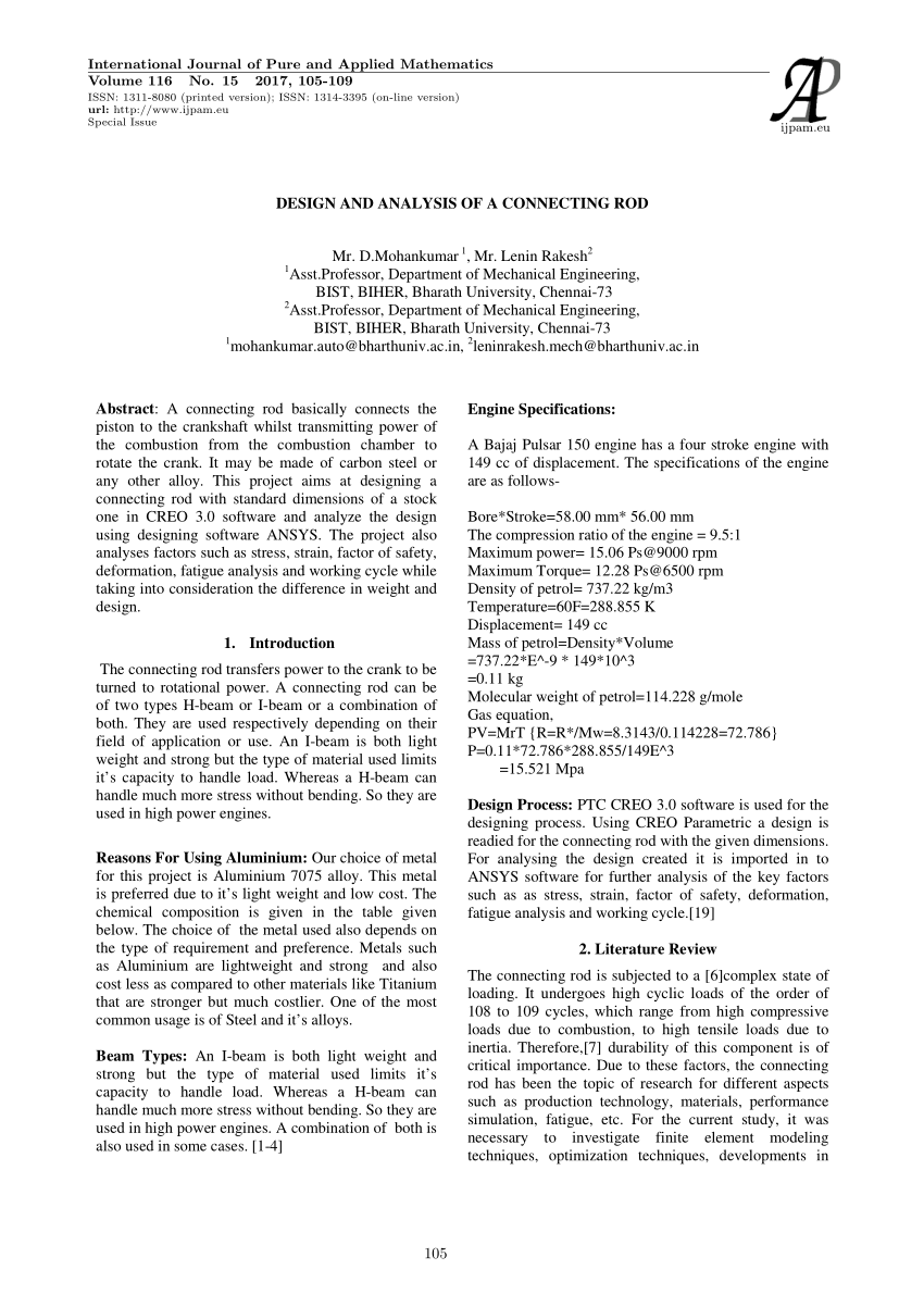
Pdf Design And Analysis Of A Connecting Rod
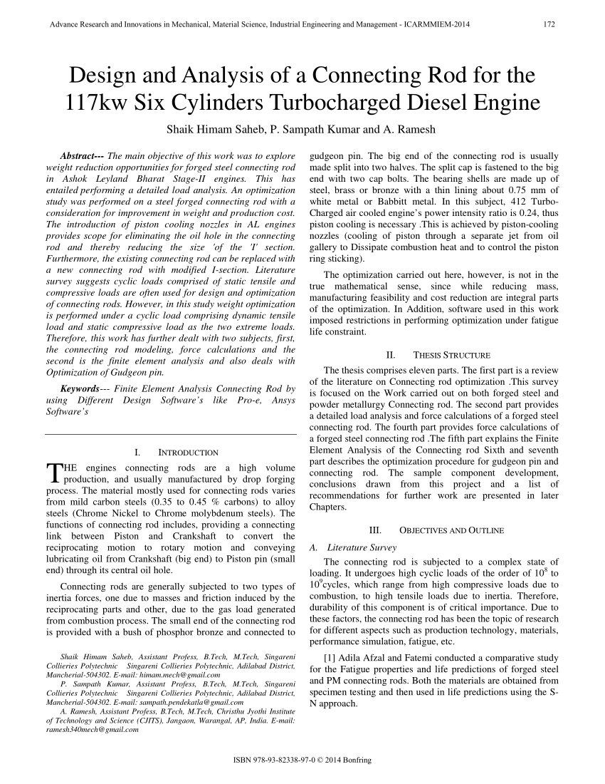
Pdf Design And Analysis Of A Connecting Rod For The 117kw Six Cylinders Turbocharged Diesel Engine
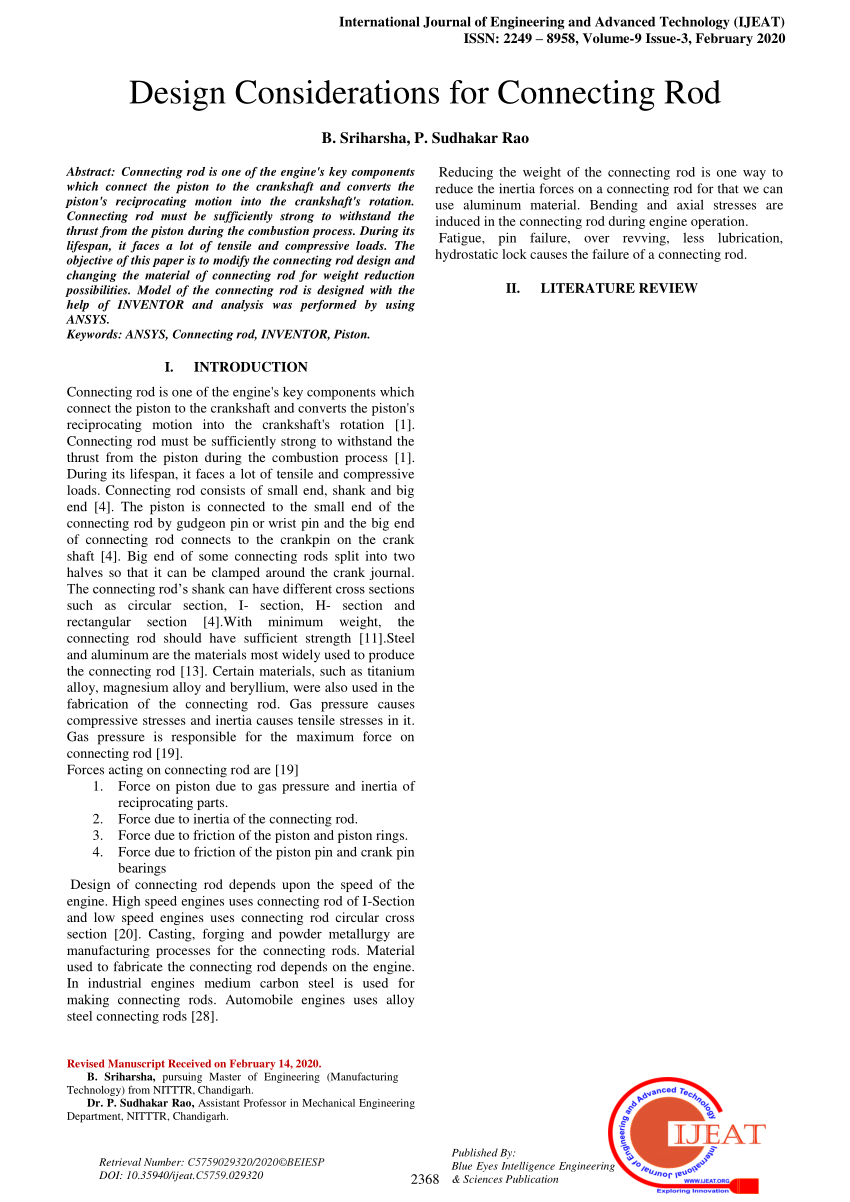
Pdf Design Considerations For Connecting Rod

Cross Sectional View Of The Connecting Rod 32 Download Scientific Diagram
Connecting Rods Parts Types Functions Applications Pdf
0 comments
Post a Comment